XR Processing and Media Centric Architectures
This clause focuses on rendering and media centric architectures. The architectures are simplified and illustrative, they only consider an XR server and an XR device to identify the functions in XR servers and XR devices that communicate and exchange information, possibly over a 5GS communication. These architectures focus on processes where the following main tasks are carried out:
- Display
- Tracking and Pose Generation
- Viewport Rendering
- Capture of real-world content
- Media encoding
- Media decoding
- Media content delivery
- 5GS communication
- Media Formats, metadata and other data delivered on communication links
- Spatial Location Processing
The section also discusses benefits and challenges of the different approaches in terms of required bitrates, latencies, reliability, etc. A main aspect to be addressed in the following are the processes that are involved in the motion-tophoton/sound latency and how the processed may impact the XR viewport rendering.
Viewport-Independent delivery
In the viewport independent delivery case, following the architecture in 3GPP TS 26.118, clause 4.3, tracking and sensor information is only processed in the XR device as shown in Figure 6.2.2-1. This means that the entire XR scene is delivered and decoded.
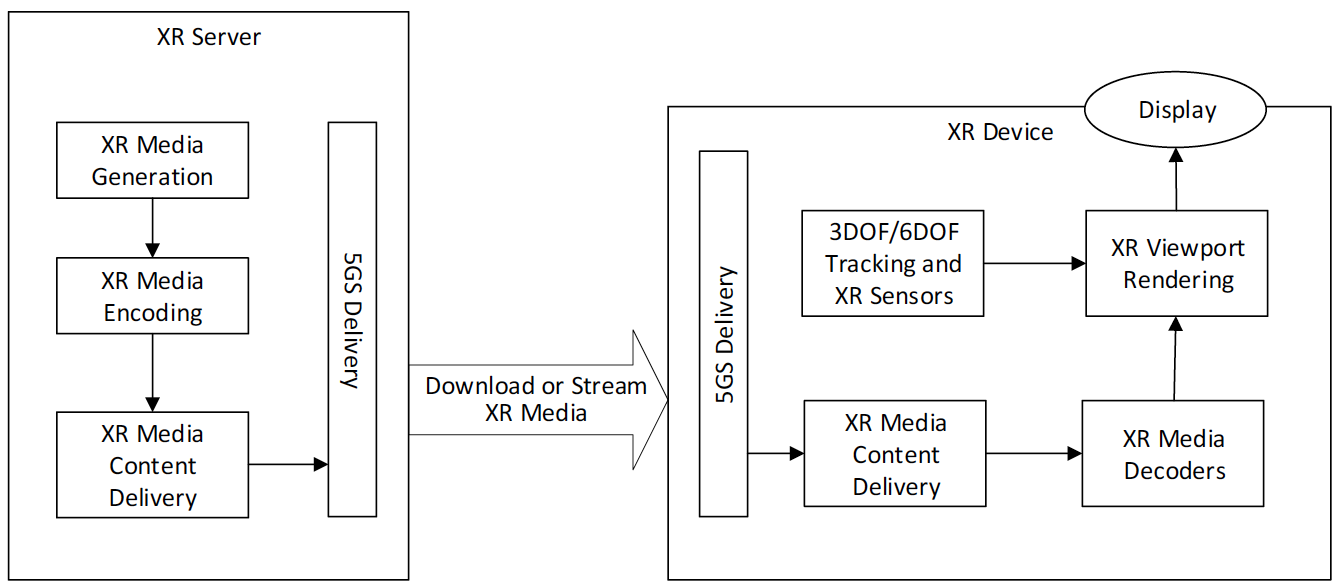 Figure 6.2.2-1: Viewport Independent Delivery
Viewport-dependent Streaming
In the viewport dependent delivery case, following the architecture in TS 26.118, clause 4.3, the tracking information is predominantly processed in the XR device, but the current pose information is provided to the XR delivery engine in order to include the pose information in the adaptive media requests. In an extension to this in the case of XR and 6DoF, the XR pose and additional information may be shared with the XR content delivery in order to only access the information that is relevant for the current viewports. According to Figure 6.2.3-1, the tracking and sensor data is processed in the XR device for XR rendering, and the media is adaptively delivered/requested based on the XR viewport. A reduced or a viewport optimized scene is delivered and also only a reduced scene is processed. Examples include an object that is not visible is not delivered, or only delivered in low quality, or that only the part of the object that is in the viewport is delivered with the highest quality.
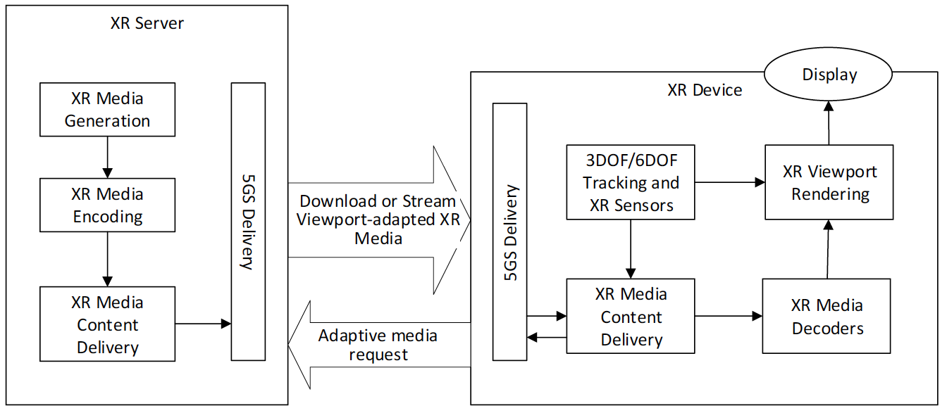 Figure 6.2.3-2 Viewport-dependent Streaming
Viewport Rendering in Network
In a architecture as shown in figure 6.2.4-1 below, the viewport is entirely rendered in the XR server. The XR server generates the XR Media on the fly based on incoming Tracking and Sensor information, for example a game engine. The generated XR media is provided for the viewport in a 2D format (flattened), encoded and delivered over the 5G network. The tracking and sensor information is delivered in the reverse direction. In the XR device, the media decoders decode the media and the viewport is directly rendered without using the viewport information.
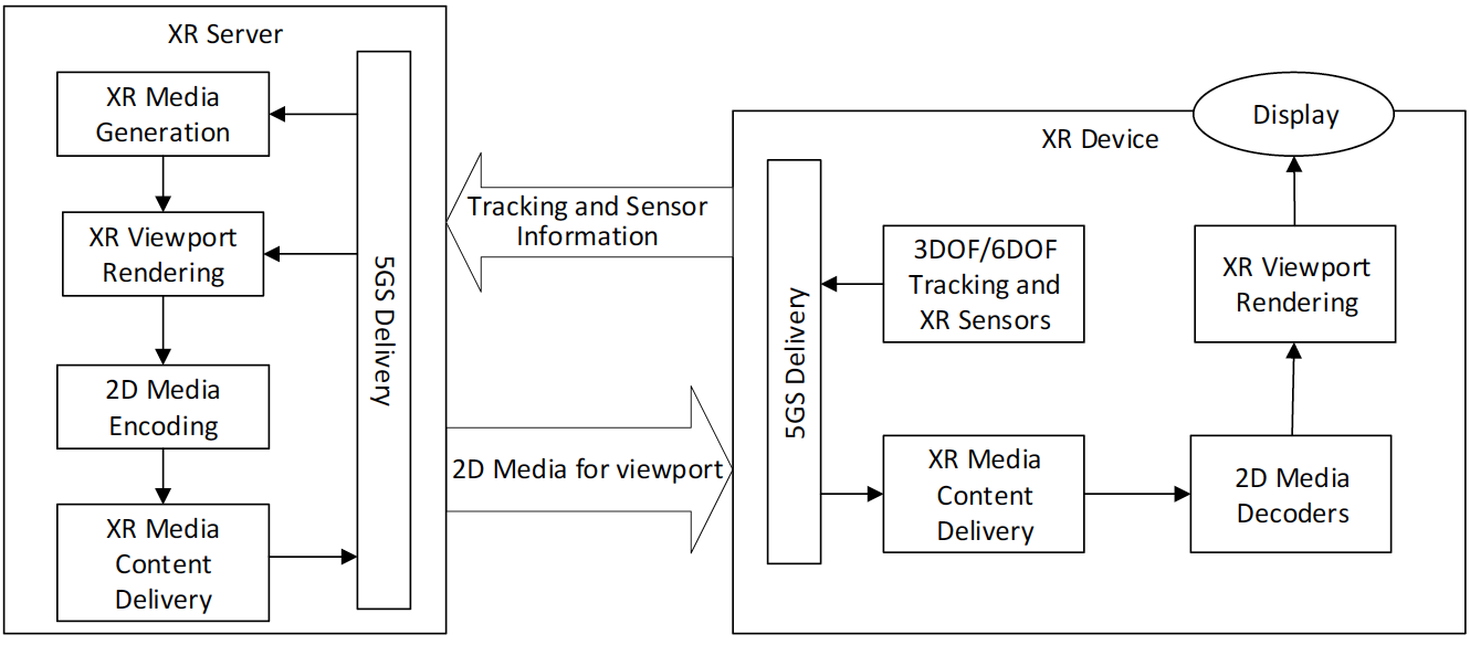 Figure 6.2.4-1 Viewport rendering in Network
Raster-based Split Rendering
Raster-based split rendering refers to the case where the XR Server runs an XR engine to generate the XR Scene based on information coming from an XR device. The XR Server rasterizes the XR viewport and does XR pre-rendering.
According to Figure 6.2.5-1, the viewport is pre-dominantly rendered in the XR server, but the device is able to do latest pose correction, for example by asynchronuous time-warping (see clause 4.1) or other XR pose correction to address changes in the pose.
- XR graphics workload is split into rendering workload on a powerful XR server (in the cloud or the edge) and pose correction (such as ATW) on the XR device
- Low motion-to-photon latency is preserved via on device Asynchronous Time Warping (ATW) or other pose correction methods.
As ATW is applied the motion-to-photon latency requirements (of at most 20 ms) are met by XR device internal processing. What determines the network requirements for split rendering is time of pose-to-render-to-photon and the roundtrip interaction delay. According to clause 4.5, the latency is typically 50-60ms. This determines the latency requirements for the 5G delivery.
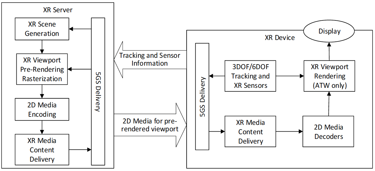 Figure 6.2.5-1: Split Rendering with Asynchronous Time Warping (ATW) Correction
Generalized XR Split Rendering
In Figure 6.2.6-1, an architecture is shown for which the XR server pre-renders the 3D scene into a simpler format to be processed by the device (e.g. it may provide additional metadata that is delivered with the pre-rendered version). The device recovers the baked media and does the final rendering based on local correction on the actual pose.
- XR graphics workload is split into rendering workload on a powerful XR server and simpler XR processing on the XR device
- This approach enables to relax the latency requirements to maintain a full immersive experience as time-critical adjustment to the correct pose is done in the device.
- this approach may provide more flexibility in terms of bitrates, latency requirements, processing, etc. than the single buffer split rendering.
Such an approach needs careful considerations on the formats of projected media and their compression with media decoders. Also important is distribution of latencies to different components of the system. More details and breakdown of the architectures is necessary. The interfaces in the device however are aligned with the general structure defined above.
In general, the similar requirements and considerations as in Raster-based split rendering apply, but a more flexible framework may be considered by providing not only 2D frame buffers, but different buffers that are split over the network.
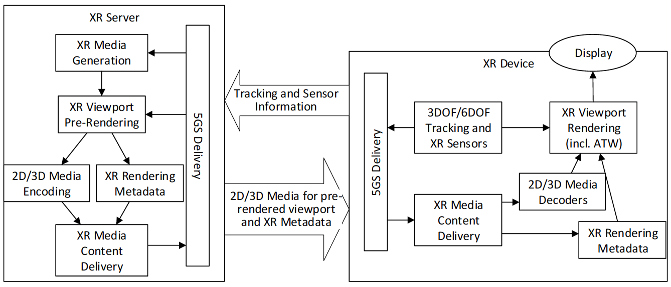 Figure 6.2.6-1: VR Split Rendering with XR Viewport Rendering in Device
XR Distributed Computing
This clause provides the architecture for extended reality applications which supports the XR split rendering. The workload for XR processing is split into workloads on XR server and the device. The below Figure 6.2.7-1 shows a high-level structure of the XR distributed computing architecture which describes their components and interfaces.
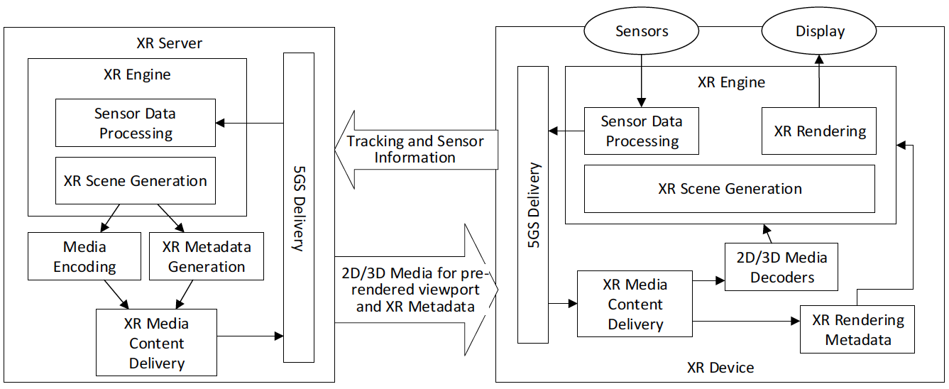 Figure 6.2.7-1: XR Distributed Computing Architecture
An XR client may have following capabilities:
- XR capture
- Sensor data processing (e.g., AR pose tracking)
- XR scene generation
- XR rendering
- 2D or 3D Media decoding
- Metadata (including scene description) processing
- 5G delivery
An XR edge server may have following capabilities:
- Sensor data processing
- XR scene generation
- 2D or 3D media encoding
- Metadata (including scene description) generation
- 5G delivery
An XR client connects to the network and joins XR rendering application. The XR client sends static device information (e.g., sensors, supported decoders, display configuration) to the XR edge server. Based on this information, the XR edge server sets up encoder and formats.
When the XR client has a set of sensors (e.g., trackers and capturing devices), it collects sensor data from sensors. The collected sensor data is processed either locally or at the XR edge server. The collected sensor data or locally processed information (e.g., a current AR pose) is sent to the XR edge server. The XR edge server uses the information to generate the XR scene. The XR edge server converts the XR scene into a simpler format as 2D or 3D media with metadata (including scene description). The media component is compressed, and the compressed media stream and metadata are delivered to the XR client. The XR client generates the XR scene by compositing locally generated or received media and metadata and renders the XR viewport via the XR display (e.g., HMD, AR glass).
For example, the XR client captures the 2D video stream from a camera and sends the captured stream to the XR edge server. The XR edge server performs the AR tracking and generates the AR scene which a 3D object is overlaid over a certain position in the 2D video based on the AR tracking information. The 3D object or 2D video for the AR scene are encoded with 2D/3D media encoders, and the scene description or the metadata is generated. The compressed media and metadata are sent to the XR client. The XR client decodes the media or metadata and generates an AR scene which overlays the 3D object in the 2D video., A user viewport is determined by horizontal/vertical field of view of the screen of a head-mounted display or any other display device. The appropriate part of AR scene for the user viewport is rendered and displayed.
XR Conversational
In Figure 6.2.8-1, a general architecture for XR conversational and conference services is depicted. As stated, these services are an extension on the current MTSI work, using the IMS for session signalling. In order to support XR conversational services (in 5G), extensions are needed in the signalling to enable VR/AR specific attributes, and the media and metadata need to support the right codecs, profiles and metadata. A new interface is the interface to the network (based) media processing. This is an interface similar to that to an SRF, but is expected to be much more extensive to support various types of media processing. This interface can be based on the work in MPEG on Network Based Media Processing.
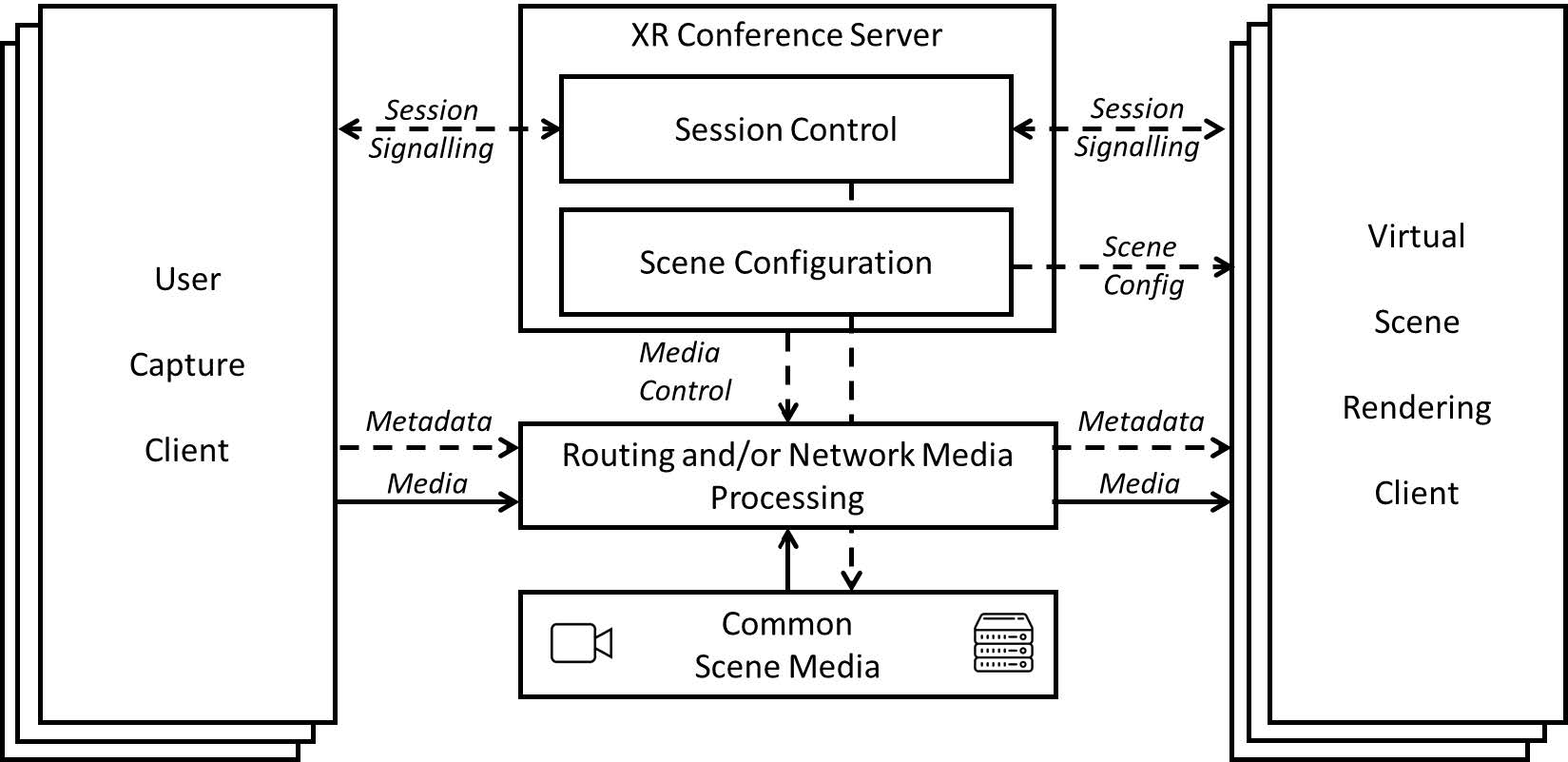 Figure 6.2.8-1 General architecture for XR conversational and conference services
Summary of Traffic Characteristics
| Archtecture | DL rate range | UL Rate range | DL PDB | UL PDB | RTT | DL PER range | UL PER range | Traffic periodicity range | Traffic file size distribution |
|---|---|---|---|---|---|---|---|---|---|
| Viewport independent streaming | 100 MBPs | HTTP requests every second. TCP handshake | See adaptive streaming | See adaptive streaming | See adaptive streaming and TCP equation | 10e-6 | 10e-6 | Almost constant | Almost constant |
| Viewport dependent streaming | 25 MBPs | More frequent HTTP requests every 100ms. TCP handshake | See adaptive streaming | See adaptive streaming | See adaptive streaming and TCP equation | 10e-6 | 10e-6 | Almost constant | Almost constant |
| Viewport Rendering in Network case 1 | 100 MBit/s | FFS | FFS | FFS | FFS | FFS | FFS | FFS | FFS |
| Viewport Rendering in Network case 2 | 1 GBit/s | FFS | FFS | FFS | FFS | FFS | FFS | FFS | FFS |
| Viewport Rendering in Network case 3 | 10 Gbit/s | FFS | FFS | FFS | FFS | FFS | FFS | FFS | FFS |
| Raster-based Split Rendering with Pose Correction | 100 Mbit/s | 500 kbit/s | 20ms | 10ms | 50ms | FFS | FFS | Almost constant | FFS |
| Generalized Split Rendering | FFS | FFS | FFS | FFS | FFS | FFS | FFS | FFS | FFS |
| XR Distributed Computing | FFS | FFS | FFS | FFS | FFS | FFS | FFS | FFS | FFS |
| XR Conversational | FFS | FFS | FFS | FFS | FFS | FFS | FFS | FFS | FFS |
| XR Conferencing Details are FFS | 3Mbit/s up to 50Mbit/s per user | 3Mbit/s up to 50Mbit/s | Allowing real time communication | Allowing real time communication | Allowing real time communication | FFS | FFS | almost constant (with peek during start-up) | 50Mb at the beginning, depending on media consumption no or almost constant |
Analysis of existing 5QIs
As a summary of the above, existing 5QIs may be used for adaptive streaming over HTTP applications.
For other types of services, new 5QIs for Uu-based communication are considered beneficial, among others.
- If other protocols than adaptive streaming over HTTP would be applied, then suitable 5QIs would be for FFS.
- New 5QIs and QoS support in 5G System for network and split rendering addressing latency requirements in the range of 10-20ms and bitrate guarantees to be able to stream 50 to 100 Mbps consistently
- More flexible 5QIs and QoS support in 5G System for generalized split rendering addressing differentiated latency requirements in the range of 10ms to several 100ms and with bitrate guarantees.
- Error rates are FFS.
- The data rate, latency and PER for different architectures as introduced in clause 6.3 are FFS.
For sidelink based communication, new PQI/QoS parameters may be defined as well. Details are FFS.