This page documents core consolidated use cases and scenarios for extended reality based on the underlying offered functionalities, the nature of the communication, interactivity and real-time requirements. These have been derived from the use cases collected in XR UC List.
| Core Use Cases and Scenarios | Use Case |
|---|---|
| Offline Sharing of 3D Objects | Use Case 1: 3D Image Messaging Use Case 2: AR Sharing Use Case 10: Online shopping from a catalogue – downloading |
| Real-time XR Sharing | Use Case 7: Real-time 3D Communication Use Case 8: AR guided assistant at remote location (industrial services) Use Case 11: Real-time communication with the shop assistant Use Case 17: AR animated avatar calls Use Case 23: 5G Shared Spatial Data |
| XR Multimedia Streaming | Use Case 3: Streaming of Immersive 6DoF Use Case 4: Emotional Streaming Use Case 20: AR Streaming with Localization Registry Use Case 21: Immersive 6DoF Streaming with Social Interaction |
| Online XR Gaming | Use Case 5: Untethered Immersive Online Gaming Use Case 6: Immersive Game Spectator Mode Use Case 22: 5G Online Gaming party |
| XR Mission Critical | Use Case 9: Police Mission Critical with AR |
| XR Conference | Use Case 12: 360-degree conference meeting Use Case 13: 3D shared experience Use Case 14: 6DOF VR conferencing Use Case 15: XR Meeting Use Case 16: Convention / Poster Session |
| Spatial Audio Multiparty Call | Use Case 18: AR avatar multi-party calls Use Case 19: Front-facing camera video multi-party calls |
The use cases are summarized in clause 5 into several core use cases and scenarios.
Offline Sharing of 3D Objects [to top]
Offline sharing is used for sharing 3D models/objects and 3D MR scenes amongst UEs. In Figure 5.2-1, UE A shares a 3D static/dynamic object with UE B. The 3D object can be a stored object downloaded by UE A from the cloud, or captured by the device using for example a depth camera. It may include additional information such as colour, texture, size, etc. of the 3D object, which is referred to as effects in the figure. Upon receiving, UE B can render this object (and/or 3D objects it has downloaded from the cloud) in the surrounding reality using an MR rendering engine; it can choose the desired effects for the 3D object. It can then capture the rendered MR scene and send it back to UE A. MMS is used for sharing the 3D object and the captured MR scene between the UEs. Note that the diagram is drawn for clarity and in reality, the capabilities of the devices may be present on each UE and not limited only to one side.
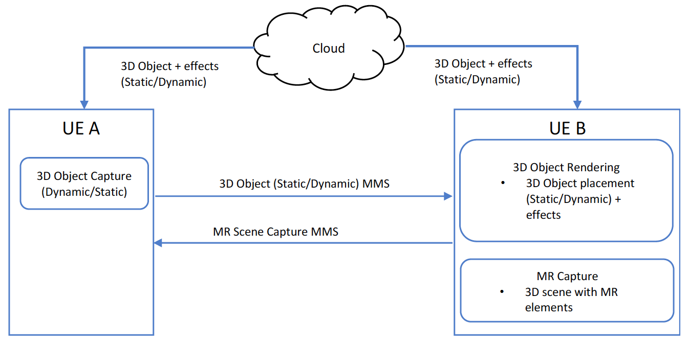 Figure 5.2-1: Offline Sharing 3D Objects and MR Scenes
Real-time XR Sharing [to top]
UE B is a device capable of XR rendering, such as AR glasses, or a mobile phone that is sending a real-time video stream of the XR experience to UE A, as illustrated in Figure 5.3-1. The XR experience is being captured and rendered by the UE B. The experience includes capture of 3D objects in a 2D scene. The rendering experience includes (real-time) 3D (static/dynamic) object placement in a 2D scene, overlay video, avatars, etc., that may be downloaded from the cloud, or sent by UE A to UE B. A bidirectional or unidirectional A/V channel may be open between the devices depending on the use case. The received objects by UE B can be influenced by UE B directly as well, based on direct or indirect input from the user. UE A also sends a real-time stream of motion signals and effects that influence the rendering of the 3D object model on UE B. Examples include: 1) head/body motion or facial expressions resulting in corresponding changes in a dynamic 3D object, e.g. an avatar, and 2) positioning and size of the 3D object within the XR scene, and subsequent changes in these parameters such as moving the object closer to a wall or making it larger. Motion data may be collected using direct input from the user interface of the device or implicitly using data from camera, gyroscopes, accelerometer, etc., including gestures. Other predefined effects for the 3D objects that can be placed on or around it can also be shared from UE A to UE B or downloaded from the cloud. Network based XR media processing may be used where required.
In a subset of this scenario where XR is not used, a 3D object may be rendered within the received video stream, e.g., a 3D representation of the head of a video call participant.
Shared AR experiences can be realized using a Spatial Computing Server (SCS), as shown in Figure 5.3-1. Collocated users with AR devices can view and interact with AR objects in a time synchronized and spatially correct manner using the SCS. Devices will send positional data updates (e.g. GPS, Wifi, visual scans etc.) to the SCS. The SCS provides spatial maps, spatial anchors and localization services to the devices. Spatial data may be crowd-sourced from multiple devices for higher accuracy in spatial mapping. It should also be possible to then assign spatial information to AR objects so they can be be dropped by users at specific locations for later discovery by other visitors.
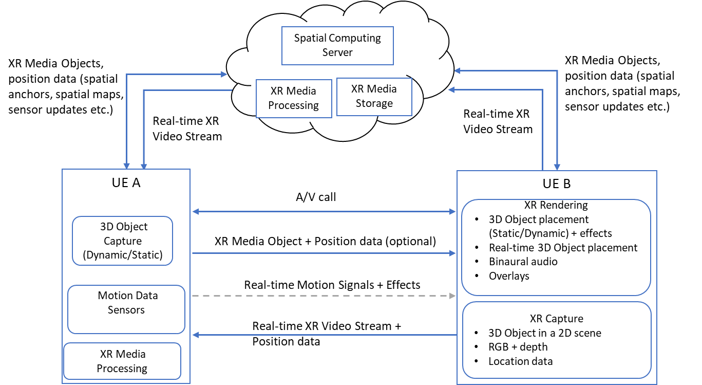 Figure 5.3-1 Real-time sharing of XR content
XR Multimedia Streaming [to top]
This category covers live and on-demand streaming of XR multimedia streams, which include 2D or Volumetric video (i.e., Constrained 6DoF) streams that are rendered in XR with binaural audio as well as 3DOF and 3DOF+ immersive A/V streams. It is illustrated in Figure 5.4-1, where UE is a device capable of receiving and rendering the type of stream in use. It is also capable of controlling the playback of these streams using input from handheld controllers, hand gestures, biometric readings, body and head movements etc., which is communicated to the content server. Control signals include pause, rewind, viewpoint selection or, in case of emotional streaming, adaptive content selection.
In another system instance, the content server can provide Inter-destination Multimedia Synchronization (n) for a group experience. A Spatial Computing Server is used by XR capable devices to register, compute, update and recall the spatial configuration of their surroundings. The service is meant for indoor spaces like a shared room or building. Appropriate surfaces may be selected for display of XR streams and saved in the Spatial Computing Server. The configuration can be shared amongst authorized users to enhance group experience when multiple users are physically sharing the same space.
A social aspect may be added to XR multimedia streaming by receiving live social media feeds, in addition to the XR media stream, that can be rendered as an overlay. Furthermore, the users may be able to see the avatars of other remote located users consuming the same media (additionally from the same viewpoint in case of multiple viewpoints) and have audio conversations with them by establishing one or more communication channels. The social aspects are added by the cloud in the Figure 5.4-1. The XR Media storage in the cloud is for fetching XR objects, e.g., avatars. The location is shared with the cloud to establish colocation within the XR. For instance, users viewing from the same viewpoint may be considered collocated when consuming synchronized media.
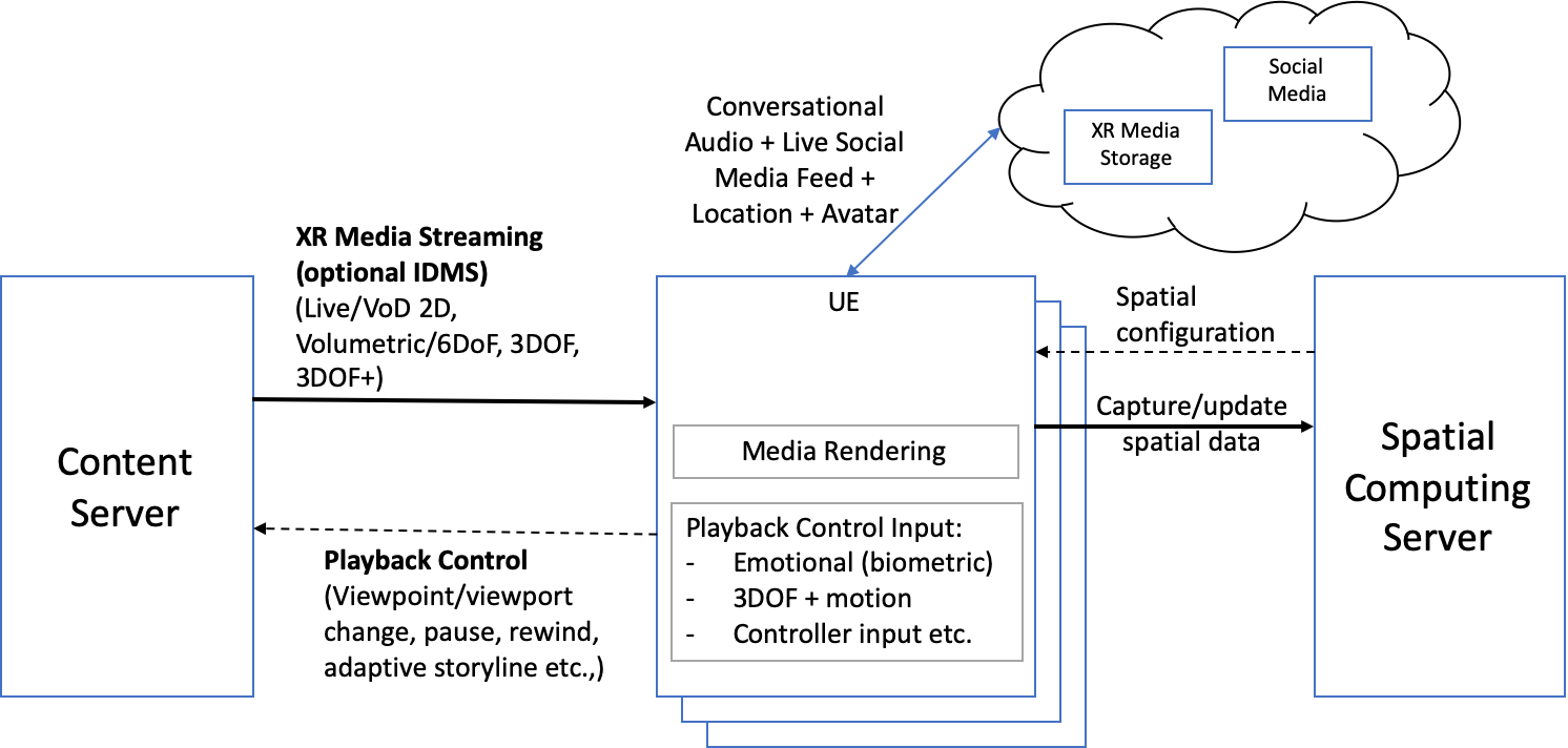 Figure 5.4-1: XR Multimedia Streaming
Online XR Gaming [to top]
The system as illustrated in Figure 5.5-1 consists of a game server capable of serving several online gamers. Each player UE receives a stream of the live game from the game server and sends control signals back to the server that influence the game play. Control signals include handheld controller inputs, biometric readings and 3DOF+ motion as required by the gameplay.
Other users may join the live game in spectator mode and can receive the stream from the perspective of an active player or a spectator view independent of other players; viewpoint changes may be possible. The spectator may enjoy an immersive experience or 2D view depending on the device. Optionally, the spectators may interact with the players through cheering or game reward systems. In a different instance, cloud rendering could be present.
In an extension, the players may be co-located at a gaming party/session using device-to-device or centralized (via gaming server) communication to enhance the user experience due to improved QoS parameters. A geofenced area may be used as the game arena for an AR gaming session, with support from a Spatial Computing Server for location registration and update and a Group discovery protocol for identifying and matching players. AI methods may be required for Image & Object Recognition, XR Lighting, Occlusion Avoidance, Shared Persistence. Spatial Computing Server receives continuous updates from the players in the arena, which are used for spatial mapping and localization. The updated spatial data (e.g., maps and player locations) is shared with the other devices and also the game server.
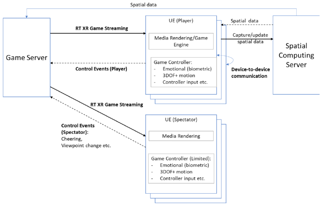 Figure 5.5-1: Online XR Gaming
XR Mission Critical [to top]
The system shown in Figure 5.6-1 is for critical missions using XR support. In this use case a team in an indoor space is equipped with mission gear that is connected to a centralized control center. The UE in the figure represents a single team member and there may be more than one device included in the misson gear, such as AR glasses, a 360 degree helmet-mounted camera, a microphone, binaural audio headphones and other sensors. The control center/conference server performs the role of mission support by providing XR graphics such as maps, text, location pointers of other team members or other objects/people in the surrounding, etc. The mixed audio of the team members as well as audio from control center is also delivered to the UE to aid team communication and coordination. One or more dronemounted cameras may also be used, which can be controlled by the control center or one of the members of the mission team. The control center is equipped with A/V processing capabilities to extract important information from the multitude of 360 degree video feeds, for instance, for identifying moving objects. All devices at the site (UEs and drones) use MCPTT to communicate.
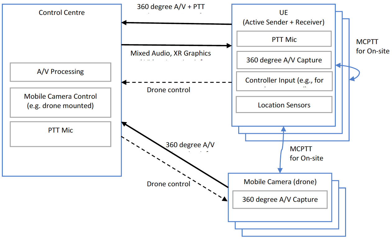 Figure 5.6-1: XR Critical Mission
XR Conference [to top]
This system caters for an XR conference with multiple physically co-located and remote participants using XR to create telepresence. The shared conference space can be, 1) a physical space that is shared by local participants and sent as an immersive stream to the remote participants, 2) a virtual space that has the same layout as the physical space so that the physically present (local) and remote participants have a similar experience while moving in the space (e.g. captured via a 360-degree camera), and 3) a virtual space that is retrieved from an application server (AS). In any of the 3 options the conference space might be extended with other Media Objects (e.g. a presentation video) retrieved from an application server (AS). The UE functionality can be split into two parts one for user media capture and one for rendering. In practice, these functions may (and usually will) be integrated within a single device (e.g. a smartphone) possibly augmented by peripheral devices like a wireless camera. Another option is that they are indeed separated, e.g. using a dedicated capture device (like a 360-degree camera) and a XR rendering device (like AR Glasses, mobile phone, VR HMD, holographic display, etc.). However, it should also be considered that some UEs will render the immersive communication experience on traditional displays.
Figure 5.7-1 illustrates the system. Virtual spaces and avatars are retrieved from the Application Server by the Conference Server. A Spatial Computing Server is used for storing the layout of the physical space, when used. Remote participants would be seen as avatars within the XR experience located at their relative position in the shared space. Alternatively, they may be represented as themselves using a live video feed and video extraction to isolate the person from the background and using a photo-realistic representation of their face in place of the HMD. The required video processing is located in the conference server in Figure 5.7-1. For example, a Network Media Processing function may perform any media and/or metadata processing that is required to place, a certain user and multiple other users consistently into a virtual environment. A typical example would be a Multipoint Control Unit (MCU) function that combines and processes the video captured from the various users in order to reduce the resource requirements of the clients. Finally, the Conference Server takes care of all the session signalling to set up channels for the exchange of media data and metadata. It performs Session Control functions for the scene configuration, network media processing and common scene media.
Remote participants are free to move around when 6DOF motion is used. The conference server processes the audio streams from the participants to create an XR experience. Participants will hear binaural audio of all participants according to their position and a 360-degree surround sound, if needed. If a physical space is used, the conference server would also receive and process input from one or multiple 360-degree A/V capture devices and RGB+depth camera. Note that when 6DOF is supported, all remote participants can move freely within the confines of the designated space, moving from one room to another when there are multiple rooms defined in the space. Using motion signals, relative positioning and location information, it would be possible for participants (local + remote) to form smaller groups for discussion within the XR space as would happen in a real space. The conversation/real-time XR stream shown in the figure is a mix of VR (remote user) or AR (local user) media, room layout (virtual/physical) and mixed binaural audio. The presentation pointer data may be sent from one of the UEs while presenting a shared presentation/poster for highlighting specific parts.
A top-view of the conference space showing its layout and the current positions of the participants can be viewed by participants and is indicated as part of the XR stream label in the figure (but as separate physical stream). The conference server should also provide IDMS.
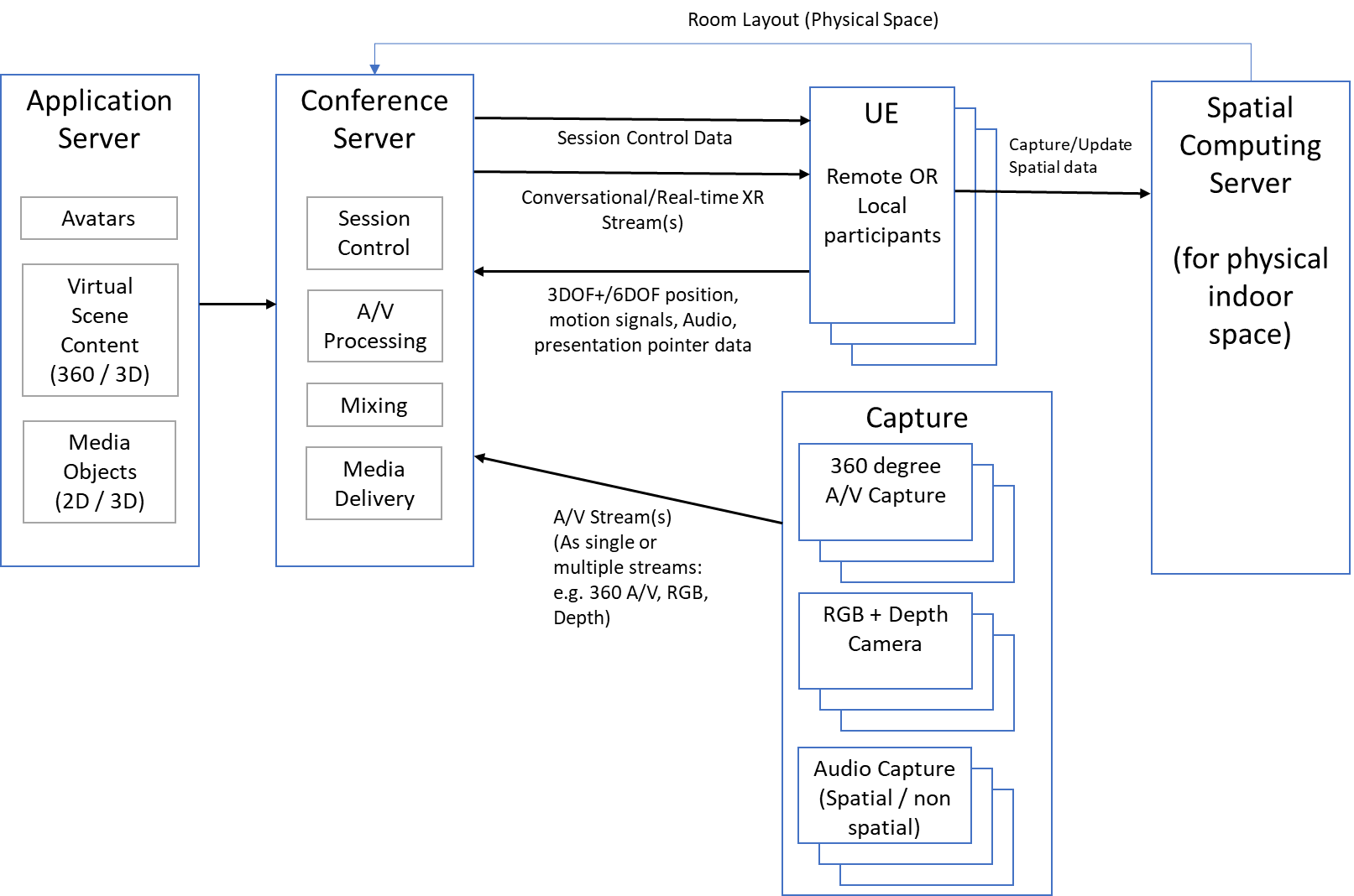 Figure 5.7-1: XR Conference
Spatial Audio Multiparty Call [to top]
The system shown in Figure 5.8-1 illustrates an AR multiparty call. Each party can see the other parties using 2D video streams captured by the front facing camera of a mobile phone. Alternatively, they can be displayed as avatars, for instance, when a pair of AR glasses are used as UE. Each party hears spatial audio with the audio of the other parties originating from where their avatar/video is placed on the display. Motion such as head turns are tracked to create a realistic impression that the audio is originating from that virtual direction.
In a special case, the avatars and the audio of the other parties on party A's display is based on their actual geolocation and the relative direction they are with respect to party A. The same would be true for all parties. UEs also have the ability to switch to PTT to suppress surrounding sound if they wish. They may use the "hear what I hear" function to send a 3D audio of their surroundings to the other parties.
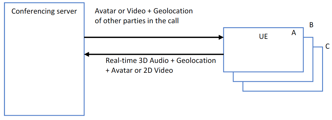 Figure 5.8-1: Spatial Audio Multiparty Call