Cell search is the procedure for a UE to acquire time and frequency synchronization with a cell and to detect the physical layer Cell ID of the cell.
A UE receives the following synchronization signals (SS) in order to perform cell search: the primary synchronization signal (PSS) and secondary synchronization signal (SSS) as defined in TS 38.211.
For a half frame with SS/PBCH blocks (SSB), the first symbol indexes for candidate SS/PBCH blocks are determined according to the SCS of SS/PBCH blocks as follows, where index 0 corresponds to the first symbol of the first slot in a half-frame.
SSB patterns applicable to different frequencies and duplexing modes
Toolbox: SSB patterns| SSB Pattern | Freq Range | SCS [kHz] | Indexes | Duplex Mode | Frequency | n | Lmax |
|---|---|---|---|---|---|---|---|
| Case A | FR1 | 15 | {2, 8}+14·n | - | ≤ 3 GHz | 0, 1 | 4 |
| > 3 GHz | 0, 1, 2, 3 | 8 | |||||
| Case B | FR1 | 30 | {4, 8, 16, 20}+28·n | ≤ 3 GHz | 0 | 4 | |
| > 3 GHz | 0, 1 | 8 | |||||
| Case C | FR1 | 30 | {2, 8}+14·n | FDD | ≤ 3 GHz | 0, 1 | 4 |
| > 3 GHz | 0, 1, 2, 3 | 8 | |||||
| TDD | < 1.88 GHz | 0, 1 | 4 | ||||
| ≥ 1.88 GHz | 0, 1, 2, 3 | 8 | |||||
| Case D | FR2 | 120 | {4, 8, 16, 20}+28·n | TDD | 0, 1, 2, 3, 5, 6, 7, 8, 10, 11, 12, 13, 15, 16, 17, 18 | 64 | |
| Case E | FR2 | 240 | {8, 12, 16, 20, 32, 36, 40, 44}+56·n | 0, 1, 2, 3, 5, 6, 7, 8 | 64 | ||
| Indexes: | 2, 8, 16, 22 | ||||||
Note:
- For Case A, Case B, and Case C, they each has two sub-patterns: one sub-pattern with 4 SSBs per set, applicable to low frequencies, another sub-pattern with 8 SSBs per set, applicable to high frequencies.
- Case A and Case C have same SSB pattern, despite the different SCS and the frequency thresholds for sub-patterns.
- For an FR1 TDD band, it may have different SSBs per set depends on the SCS configuration. E.g., band n39 and n41 lie between 1.88GHz ~ 3GHz. They both support patterns Case A and Case C. When using Case A, the frequency is below the threshold, the first sub-pattern is effective with Lmax = 4. When using Case C, the frequency is above the threshold, the second sub-pattern is effective with Lmax = 8.
Figure below shows the SSB patterns. For the ones with two sub-patterns, we use 'X0' and 'X1' to denote the two sub-patterns, where X can be 'A', 'B', or 'C'. 'X0' applies to low frequency, 'X1' applies to high frequency.
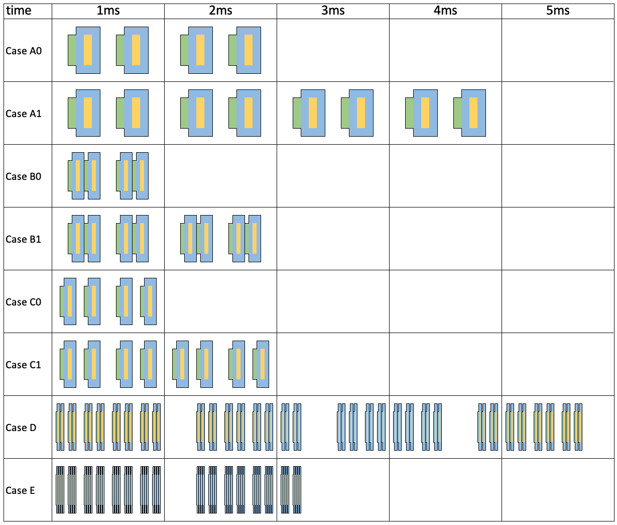
SSB patterns
How to decide the SSB pattern to use
- if SCS for SS/PBCH blocks is unknown, the applicable cases for a cell depend on a respective frequency band, as provided in TS 38.101 Table 5.4.3.3-1. For bands with two possible SCSs, UE needs to try both SCS hypothesis to detect the SSB.
- if the SCS of SS/PBCH blocks is provided by ssbSubcarrierSpacing:
- if SCS equals 15 / 120 / 240 kHz, Case A / D / E shall be used, respectively.
- if SCS equals 30 kHz,
- for frequency bands with only 15 kHz SS/PBCH block SCS as specified in TS 38.101 Table 5.4.3.3-1: Case B shall be used. Otherwise,
- the case is jointly decided by the SCS and the band, which can be either Case B or Case C.
How to obtain SSB index and cell timing after SSB is detected
- An SSB can be identified using a combination of System Frame Number (SFN), the Half Radio Frame flag, and the SSB index.
- SFN is indiated by 10 bits (0 ~ 1023). The 6 Most Significant Bits (MSB) of the SFN occupy the first 6 bits of Master Information Block (MIB); the 4 Least Significant Bits (LSB) occupy the first 4 bits of PBCH payload.
- The Half Radio Frame flag is communicated in PBCH, it occupies the 5th bit of PBCH payload. If the SSB pattern has only 4 SSBs per set, the Half Radio Frame flag can also be deducted from the PBCH DMRS scrambling sequence: the 3rd bit of the sequence index.
- The SSBs in a half frame are indexed in an ascending order in time from 0 to Lmax-1:
- When there are 4 SSBs in the set (Case A0, B0, C0), the SSB index corresponds to the first two bits of DMRS sequence index.
- When there are 8 SSBs in the set (Case A1, B1, C1), the SSB index is same as the DMRS sequence index.
- When there are 64 SSBs in the set (Case D, E), the 3 MSB bits are taken from the 8th/7th/6th bits of PBCH payload, and the 3 LSB bits correspond to the DMRS sequence index.
| Interpretation of parameters | ||||||||||||||||||
|---|---|---|---|---|---|---|---|---|---|---|---|---|---|---|---|---|---|---|
| Lmax | MIB[5~0] | PBCH[7~0] | DMRS sequence index | |||||||||||||||
| s5 | s4 | s3 | s2 | s1 | s0 | α7 | α6 | α5 | α4 | α3 | α2 | α1 | α0 | b2 | b1 | b0 | ||
| 4 | MSB of SFN | - | MSB of kSSB | half-frame bit | LSB of SFN | half-frame bit | SSB index | |||||||||||
| 8 | LSB of SSB index | |||||||||||||||||
| 64 | MSB of SSB index | |||||||||||||||||
| Example | ||||||||||||||||||
| SSB Pattern | Lmax | MIB[5~0] | PBCH[7~0] | DMRS sequence index | ||||||||||||||
| 4 | ||||||||||||||||||
| 0 | 0 | 0 | 0 | 0 | 1 | 0 | 0 | 0 | 1 | 0 | 0 | 0 | 1 | 1 | 0 | 0 | ||
| Result | ||||||||||||||||||
| SCS [kHz] | SSB index | Symbol index within SSB set | SFN | Slot | Symbol | |||||||||||||
| 15 | 0 | 2 | 17 | 5 | 2 | |||||||||||||
How to decide the periodicity of the SSB burst set
- Serving cell: ssb-periodicityServingCell, The SSB periodicity (5/10/20/40/80/160) in ms for the rate matching purpose. If the field is absent, UE assumes a periodicity of 5 ms.
- Initial cell selection: assumes a periodicity of 20ms.
- Neighbor cell: SSB-MTC, which is used to configure measurement timing configurations, i.e., timing occasions at which the UE measures SSBs. The periodicity can be 5/10/20/40/80/160 ms.
How to determine the frequency location of Type0-PDCCH CSS CORESET
- First UE decode MIB, and obtain the value of kSSB from MIB.
- If kSSB ≤ 23 for FR1 or kSSB ≤ 11 for FR2, UE follows TS 38.213 Clause 13 to determine the CORESET;
- If kSSB > 23 for FR1 or kSSB > 11 for FR2, the CORESET is not present.
- the CORESET for Type0-PDCCH CSS set may be provided by PDCCH-ConfigCommon.
With carrier aggregation
For a UE configured to operate with carrier aggregation over a set of cells in a frequency band of FR2 or with frequency contiguous carrier aggregation over a set of cells in a frequency band of FR1, if the UE is provided SCS values by ssbSubcarrierSpacing for receptions of SS/PBCH blocks on any cells from the set of cells, the UE expects the SCS values to be same.
For a serving cell without transmission of SS/PBCH blocks, a UE acquires time and frequency synchronization with the serving cell based on receptions of SS/PBCH blocks on the PCell, or on the PSCell, of the cell group for the serving cell.