| Parameter | Value |
|---|---|
| μ | |
| SearchSpace.monitoringSlotPeriodicity | |
| SearchSpace.monitoringSlotOffset | |
| SearchSpace.duration | |
| SearchSpace.monitoringSymbolsWithinSlot | |
| ControlResourceSet.duration |
PDCCH monitoring slots
| nf | nslot within a subframe | |||||||||||||||||||
|---|---|---|---|---|---|---|---|---|---|---|---|---|---|---|---|---|---|---|---|---|
| 0 | 1 | 2 | 3 | 4 | 5 | 6 | 7 | 8 | 9 | 10 | 11 | 12 | 13 | 14 | 15 | 16 | 17 | 18 | 19 | |
| 0 | 2 | 3 | 4 | 5 | 12 | 13 | 14 | 15 | ||||||||||||
| 1 | 2 | 3 | 4 | 5 | 12 | 13 | 14 | 15 | ||||||||||||
| 2 | 2 | 3 | 4 | 5 | 12 | 13 | 14 | 15 | ||||||||||||
| 3 | 2 | 3 | 4 | 5 | 12 | 13 | 14 | 15 | ||||||||||||
PDCCH monitoring symbols
| isymbol | 0 | 1 | 2 | 3 | 4 | 5 | 6 | 7 | 8 | 9 | 10 | 11 | 12 | 13 |
|---|---|---|---|---|---|---|---|---|---|---|---|---|---|---|
| Monitor PDCCH? | Y | Y | Y | Y | Y | Y |
RNTI
Different DCIs are scrambled by different kinds of RNTIs. This is used to address a specific UE, a group of UEs or all UEs:
- SI-RNTI and P-RNTI have fixed values to all UEs
- INT-RNTI and SFI-RNTI are common to a group of UEs
- Other RNTIs are dedicated per UE
| RNTI | DCI format | Application | Value | |
|---|---|---|---|---|
| hex | decimal | |||
| SI-RNTI | 1_0 | PDSCH for System Information (SI) | FFFF | 65535 |
| P-RNTI | 1_0 | PDSCH for Paging messages | FFFE | 65534 |
| RA-RNTI | 1_0 | PDSCH for Random Access Response (RAR, MSG2) | 0001 to FFEF | 0001 - 65519 |
| TC-RNTI | 0_0, 1_0 | PUSCH for MSG3 re-transmissions, PDSCH for MSG4 | ||
| C-RNTI | 0_0, 0_1, 1_0, 1_1 | PUSCH and PDSCH for control/data plane signaling | ||
| MCS-C-RNTI | 0_0, 0_1, 1_0, 1_1 | dynamic selection of low spectral efficiency MCS table for PDSCH and PUSCH | ||
| CS-RNTI | 0_0, 0_1, 1_0, 1_1 | configured grant scheduling for PUSCH, semi-persistent scheduling for PDSCH | ||
| TPC-PUSCH-RNTI | 2_2 | PUSCH power control command | ||
| TPC-PUCCH-RNTI | 2_2 | PUCCH power control command | ||
| TPC-SRS-RNTI | 2_3 | SRS power control command | ||
| INT-RNTI | 2_1 | Interruption signalled using pre-emption indications | ||
| SFI-RNTI | 2_0 | dynamic changes to the slot format signalled using SLot Format Indicator (SFI) | ||
| SP-CSI-RNTI | 0_1 | activate/deactivate semi-persistent CSI reporting | ||
CORESET
Base station transmits PDCCH to UE using Resource Elements (REs) within a Control Resource Set (CORESET). For each DL BWP configured to a UE in a serving cell, a UE can be provided by higher layer signalling with P ≤ 3 CORESETs. For each CORESET, the UE is provided the following by ControlResourceSet:
Parameter structure of ControlResourceSet| Parameter | Value | Descriptions | ||
|---|---|---|---|---|
| controlResourceSetId | 0..11 | coreset index, unique among the BWPs of a serving cell | ||
| frequencyDomainResources | BIT STRING (SIZE 45) | a set of resource blocks, each bit corresponds a group of 6 RBs | ||
| duration | 1, 2, 3 | contiguous time duration of the CORESET in number of symbols | ||
| cce-REG-MappingType | CHOICE | |||
| interleaved | nonInterleaved | |||
| reg-BundleSize | 2, 3, 6 | - | number of REGs bundled together | |
| interleaverSize | 2, 3, 6 | |||
| shiftIndex | 0..274 | when absent, use physCellId | ||
| precoderGranularity | sameAsREG-bundle, allContiguousRBs | precoder granularity in frequency domain | ||
| tci-StatesPDCCH-ToAddList | SEQUENCE(SIZE 1..64) of TCI-StateId | a subset of the TCI states defined in pdsch-Config | ||
| tci-StatesPDCCH-ToReleaseList | SEQUENCE(SIZE 1..64) of TCI-StateId | |||
| tci-PresentInDCI | enabled | field present: TCI field is present in DL-related DCIfield absent: TCI field is absent in DL-related DCI | ||
| pdcch-DMRS-ScramblingID | 0..65535 | DM-RS scrambling sequence initialization value. When absent, use physCellId | ||
Detailed descriptions of the CORESET configurations:
- controlResourceSetId of 0 is used for the CORESET configured by the controlResourceSetZero IE within MIB and within the ServingCellConfigCommon IE.
- the CORESET duration is semi-statically configured. This differs from LTE where a UE needs to decode PCFICH before knowing how many symbols are used for PDCCH. Removing PCFICH in NR helps to speed up the decoding process.
- Note: CORESET configuration does not specify the start symbol of the PDCCH (which is defined within SearchSpace configuration.
- PDCCH and its DMRS are transmitted using a single antenna port 2000. Base station can apply precoding to this antenna port to generate a beam in the direction of the UE. precoderGranularity provides UE with information regarding the frequency selectivity of the precoding applied by the base station.
- When precoderGranularity = sameAsREG-bundle: UE assumes that base station applies the same precoding weights to RBs within a REG bundle.
- When precoderGranularity = allContiguousRBs: UE assumes that base station applies the same precoding weights to all RBs belonging to contiguous REG bundles. a UE does not expect:
- to be configured a set of resource blocks of a CORESET that includes more than four sub-sets of resource blocks that are not contiguous in frequency
- any RE of a CORESET to overlap with any RE determined from lte-CRS-ToMatchAround or with any RE of a SS/PBCH block
- For each CORESET in a DL BWP of a serving cell, a respective frequencyDomainResources provides a bitmap. The bits of the bitmap have a one-to-one mapping with non-overlapping groups of 6 consecutive PRBs, in ascending order of the PRB index in the DL BWP bandwidth of BWP PRBs with starting common RB position where the first common RB of the first group of 6 PRBs has common RB index .
- A UE is also provided with Quasi Co-Location (QCL) information to support PDCCH decoding. QCL means that transmissions from different antenna ports share same common characteristics. To determine the quasi co-location relation of CORESET and the reference signals:
- For a CORESET other than a CORESET with index 0:
- if a UE has not been provided a configuration of TCI state(s) for the CORESET, or has been provided initial configuration of more than one TCI states for the CORESET but has not received a MAC CE activation command for one of the TCI states: UE assumes that the DM-RS antenna port associated with PDCCH receptions is quasi co-located with the SS/PBCH block the UE identified during the initial access procedure
- if a UE has been provided a configuration of more than one TCI states for the CORESET as part of Reconfiguration with sync procedure but has not received a MAC CE activation command for one of the TCI states: UE assumes that the DM-RS antenna port associated with PDCCH receptions is quasi colocated with the SS/PBCH block or the CSI-RS resource the UE identified during the random access procedure initiated by the Reconfiguration with sync procedure.
- if a UE is provided a single TCI state for a CORESET, or if the UE receives a MAC CE activation command for one of the provided TCI states for a CORESET, the UE assumes that the DM-RS antenna port associated with PDCCH receptions in the CORESET is quasi co-located with the one or more DL RS configured by the TCI state.
- For a CORESET with index 0, the UE assumes that a DM-RS antenna port for PDCCH receptions in the CORESET is quasi co-located with:
- the one or more DL RS configured by a TCI state, where the TCI state is indicated by a MAC CE activation command for the CORESET, if any, or
- a SS/PBCH block the UE identified during a most recent random access procedure not initiated by a PDCCH order that triggers a contention-free random access procedure, if no MAC CE activation command indicating a TCI state for the CORESET is received after the most recent random access procedure
- the UE expects that QCL-TypeD of a CSI-RS in a TCI state indicated by a MAC CE activation command for the CORESET is provided by a SS/PBCH block:
- if the UE receives a MAC CE activation command for one of the TCI states, the UE applies the activation command in the first slot that is after slot where k is the slot where the UE would transmit a PUCCH with HARQ-ACK information for the PDSCH providing the activation command and μ is the SCS configuration for the PUCCH. The active BWP is defined as the active BWP in the slot when the activation command is applied.
- For a CORESET other than a CORESET with index 0:
Search space
A set of PDCCH candidates for a UE to monitor is defined in terms of PDCCH search space sets. A search space set can be a Common Search Space (CSS) set or a UE-specific Search Space (USS) set. A UE monitors PDCCH candidates in one or more of the following search spaces sets:
Search space set types| Type | Scrambling RNTI | DCI format | Used for | Configured by | cell | |
|---|---|---|---|---|---|---|
| CSS | Type0 | SI-RNTI | 1_0 | SIB | MIB or SIB1 | PCell of MCG |
| Type0A | SI-RNTI | 1_0 | other SIBs | searchSpaceOtherSystemInformation | PCell of MCG | |
| Type1 | RA-RNTI, TC-RNTI, C-RNTI | 0_0, 1_0 | MSG2, MSG4 | ra-SearchSpace | PCell | |
| Type2 | P-RNTI | 1_0 | paging | pagingSearchSpace | PCell of MCG | |
| Type3 | INT-RNTI, SFI-RNTI, TPC-XXX-RNTI | 0_0, 1_0, 2_0, 2_1, 2_2, 2_3 | MISC | SearchSpace with searchSpaceType = common | any | |
| C-RNTI, MCS-C-RNTI, CS-RNTI | PCell | |||||
| USS | C-RNTI, MCS-C-RNTI, SP-CSI-RNTI, CS-RNTI | 0_0, 0_1, 1_0, 1_1 | UE specific signaling | SearchSpace with searchSpaceType = ue-Specific | any | |
While the full list of possible CCE aggregation levels is already defined in TS 38.211 Table 7.3.2.1-1: Supported PDCCH aggregation levels, for Type0, Type0A and Type2 PDCCH CSS, the CCE aggregation levels and the number of PDCCH candidates per CCE aggregation level are given in Table 10.1-1:
Table 10.1-1: CCE aggregation levels and maximum number of PDCCH candidates per CCE aggregation level for CSS sets configured by searchSpaceSIB1| CCE Aggregation Level | Number of Candidates | Resource Element Groups (REG) | Resource Elements (RE) |
|---|---|---|---|
| 4 | 4 | 24 | 288 |
| 8 | 2 | 48 | 576 |
| 16 | 1 | 96 | 1152 |
Each search space is mapped to a specific Control Resource Set (CORESET). The CORESET defines the set of Resource Blocks and the number of symbols available to the search space set. For each DL BWP configured to a UE in a serving cell, the UE is provided by higher layers with S ≤ 10 search space sets where, for each search space set from the S search space sets, the UE is provided the following by SearchSpace:
Parameter structure of SearchSpace| Parameter | Details | |||||
|---|---|---|---|---|---|---|
| searchSpaceId | 0..39 | |||||
| controlResourceSetId | 0..11 | |||||
| monitoringSlotPeriodicityAndOffset | CHOICE | |||||
| 1 slot | 10 slots | 0..9 | 160 slots | 0..159 | ||
| 2 slots | 0..1 | 16 slots | 0..15 | 320 slots | 0..319 | |
| 4 slots | 0..3 | 20 slots | 0..19 | 640 slots | 0..639 | |
| 5 slots | 0..4 | 40 slots | 0..39 | 1280 slots | 0..1279 | |
| 8 slots | 0..7 | 80 slots | 0..79 | 2560 slots | 0..2559 | |
| duration | 2..2559 | |||||
| monitoringSymbolsWithinSlot | BIT STRING (SIZE 14) | |||||
| nrofCandidates | aggregationLevel1 | {0, 1, 2, 3, 4, 5, 6, 8} | ||||
| aggregationLevel2 | ||||||
| aggregationLevel4 | ||||||
| aggregationLevel8 | ||||||
| aggregationLevel16 | ||||||
| searchSpaceType | CHOICE | |||||
| common | ue-Specific | |||||
| dci-Format0-0-AndFormat1-0 | dci-Formats | {formats0-0-And-1-0, formats0-1-And-1-1} | ||||
| dci-Format2-0 | nrofCandidates-SFI | aggregationLevel1 | {1, 2} | |||
| aggregationLevel2 | ||||||
| aggregationLevel4 | ||||||
| aggregationLevel8 | ||||||
| aggregationLevel16 | ||||||
| dci-Format2-1 | ||||||
| dci-Format2-2 | ||||||
| dci-Format2-3 | dummy1 | sl{1, 2, 4, 5, 8, 10, 16, 20} | ||||
| dummy2 | {1, 2} | |||||
Detailed descriptions of the SearchSpace configuration:
- searchSpaceId: s, an identify for the Search Space Set being configured
- controlResourceSetId: an association between the search space set s and a CORESET p
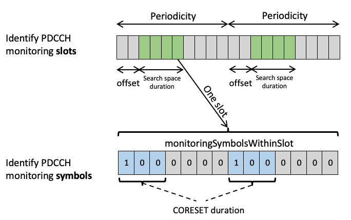
- monitoringSlotPeriodicityAndOffset: a PDCCH monitoring periodicity of ks slots and a PDCCH monitoring offset of os slots
- duration: Ts < ks slots indicating a number of slots that the search space set s exists
- monitoringSymbolsWithinSlot: a PDCCH monitoring pattern within a slot, indicating first symbol(s) of the CORESET within a slot for PDCCH monitoring. It is a bit string with each bit representing one symbol within a slot. The bit(s) set to one identify the first OFDM symbol(s) of the control resource set within a slot.
- nrofCandidates: , a number of PDCCH candidates per CCE aggregation level L. Base station uses this IE to focus the UE blinddecoding attempts to the most appropirate aggregation levels. E.g. if UE signal quality is low, base station may set 0 candidate for low aggregation levels.
- searchSpaceType: an indication that search space set s is a CSS set or a USS set
- if search space set s is a CSS set:
- dci-Format0-0-AndFormat1-0: an indication to monitor PDCCH candidates for DCI format 0_0 and DCI format 1_0
- dci-Format2-0: an indication to monitor one or two PDCCH candidates for DCI format 2_0 and a corresponding CCE aggregation level
- dci-Format2-1: an indication to monitor PDCCH candidates for DCI format 2_1
- dci-Format2-2: an indication to monitor PDCCH candidates for DCI format 2_2
- dci-Format2-3: an indication to monitor PDCCH candidates for DCI format 2_3
- if search space set s is a USS set:
- dci-Formats: an indication to monitor PDCCH candidates either for DCI format 0_0 and DCI format 1_0, or for DCI format 0_1 and DCI format 1_1
- if search space set s is a CSS set:
Restrictions of SearchSpace configuration:
- If the monitoringSymbolsWithinSlot indicates to a UE to monitor PDCCH in a subset of up to three consecutive symbols that are same in every slot where the UE monitors PDCCH for all search space sets, the UE does not expect to be configured with a PDCCH SCS other than 15 kHz if the subset includes at least one symbol after the third symbol.
- A UE does not expect to be provided a first symbol and a number of consecutive symbols for a CORESET that results to a PDCCH candidate mapping to symbols of different slots.
- A UE does not expect any two PDCCH monitoring occasions on an active DL BWP, for a same search space set or for different search space sets, in a same CORESET to be separated by a non-zero number of symbols that is smaller than the CORESET duration.
A UE determines a PDCCH monitoring occasion on an active DL BWP from the PDCCH monitoring periodicity, the PDCCH monitoring offset, and the PDCCH monitoring pattern within a slot:
- For search space set s, the UE determines that a PDCCH monitoring occasion(s) exists in a slot with number in a frame with number nf if
- The UE monitors PDCCH candidates for search space set s for Ts consecutive slots, starting from slot , and does not monitor PDCCH candidates for search space set s for the next ks - Ts consecutive slots.
Within the search space, a UE performs blind decoding because it does not know the aggregation level, the position of the PDCCH within the set of CCEs, or the format, size of the DCI. To help limit the processing requirement of the UE, 3GPP provides in
- Table 10.1-2: the maximum number of monitored PDCCH candidates, , for a DL BWP with SCS configuration μ for a UE per slot for operation with a single serving cell.
- Table 10.1-3: the maximum number of non-overlapped CCEs, , for a DL BWP with SCS configuration μ that a UE is expected to monitor corresponding PDCCH candidates per slot for operation with a single serving cell. CCEs for PDCCH candidates are non-overlapped if they correspond to:
- different CORESET indexes, or
- different first symbols for the reception of the respective PDCCH candidates.
| Table 10.1-2 | Table 10.1-3 | |
|---|---|---|
| μ | Maximum number of monitored PDCCH candidatesper slot and per serving cell | Maximum number of non-overlapped CCEsper slot and per serving cell |
| 0 | 44 | 56 |
| 1 | 36 | 56 |
| 2 | 22 | 48 |
| 3 | 20 | 32 |