Bluetooth devices operate in the unlicensed 2.4 GHz Industrial, Scientific and Medical (ISM) band. Many other technologies utilize the ISM band, including wireless LAN, cordless phones, and microwave ovens. The ISM band is also close enough to other frequency bands that Bluetooth devices may be an interferer of or a victim of other technologies.
Radios may be collocated or non-collocated. The term "collocated" is a loose one - in this specification, collocated radios are assumed to be in the same product (a Multi-Radio Terminal or MRT) and may have mechanisms to coordinate their activity in order to mitigate interference.
Determining the amount of expected isolation between radios is important for choosing an appropriate coexistence mechanism. With sufficient isolation, frequency division duplexing (FDD) techniques are the most efficient. With insufficient isolation or a shared antenna, time division duplexing (TDD) techniques need to be used. In many cases, a combination of FDD and TDD techniques are required to achieve acceptable levels of performance.
This specification supports a variety of features that help mitigate interference to other devices and to minimize interference from other devices. Broadly, the types of solutions fall into the following categories:
Interference mitigation types| Type | Description |
|---|---|
| Frequency division | Simultaneous use of multiple radios enabled by filters and/or isolation |
| Time division | One radio may transmit or receive at a time through scheduling or prioritization |
| Time alignment | Activities of the collocated radios are aligned in the time domain to optimize performances by avoiding conflicting activities. E.g. Transmissions of multiple radios may occur simultaneously, multiple receptions may occur simultaneously, but it is not possible to transmit and receive simultaneously |
| Hybrid frequency and time division | Use of frequency division, time alignment, and time division techniques depending on the relative frequencies in use by the radios, filters and isolation |
CORE FEATURES SUPPORTING COEXISTENCE AND COLLOCATION
| Feature | Version introduced | Description |
|---|---|---|
| Adaptive Frequency Hopping | 1.2 | Allows devices to reduce the number of channels used in a piconet in order to avoid interferers |
| HCI Set Host Channel Classification | 1.2 | Allows a Host to inform the local Bluetooth Controller of the channels that are occupied by a collocated technology |
| Enhanced SCO (eSCO) | 1.2 | Added retransmissions to SCO for the purpose of combating interference |
| MWS Coexistence Signaling | CSA3 | Provides a standardized interface between collocated radios for communicating information necessary to enable some coexistence techniques |
| Piconet Clock Adjust | 4.1 | Allows a Bluetooth device to align the piconet clock with an external technology, e.g. Long Term Evolution (LTE) |
| Train Nudging | 4.1 | Provides a mechanism to improve the success rate of page and inquiry when the slots to receive the respective responses are periodically not available |
| Generalized Interlaced Scanning | 4.1 | Provides a mechanism to improve the success rate of page scan and inquiry scan when some slots are periodically not available for scanning |
| Slot Availability Mask | 5.0 | Provides a mechanism for two Bluetooth devices to indicate to each other the availability of their time slots |
ADAPTIVE FREQUENCY HOPPING
Adaptive Frequency Hopping (AFH) allows Bluetooth devices to improve their immunity to interference from and avoid causing interference to other devices in the 2.4 GHz ISM band. The basic principle is that Bluetooth channels are classified into two categories, used and unused, where used channels are part of the hopping sequence and unused channels are replaced in the hopping sequence by used channels in a pseudo-random way. This classification mechanism allows for the Bluetooth device to use either all or fewer than the 79 channels available. The minimum number of channels allowed by the Bluetooth specification is 20.
The specification defines the aspects of AFH necessary to ensure interoperability, including the hopping kernel, Baseband behavior, Link Manager Protocol (LMP) commands, and Host Controller interface (HCI) commands and events required to change and configure hopping sequences. The Bluetooth Specification also defines a mechanism that allows for a slave to eport channel classification information to the master.
Adaptive Frequency Hopping utilizes metrics obtained through many sources. These metrics are analyzed and then the resulting Channel_Map is used by the adaptive frequency hopping kernel. The metrics may come from over-theair measurements, data supplied by the Host (via the HCI_Set_AFH_Host_Channel_Classification command), or reports by the slave or from other hardware coexistence interfaces. While AFH is a critical element in coexistence, it is not enough in some circumstances.
MOBILE WIRELESS STANDARDS (MWS) COEXISTENCE
Significant interference can be present between the Bluetooth radio and a collocated MWS radio operating in frequency bands adjacent to the 2.4 GHz ISM band. This interference can prevent one radio from receiving while the other radio is transmitting.
The “Filter recommendations for Coexistence with LTE and WiMAX” whitepaper describes filter specifications that, in some cases, can reduce collocated interference to an acceptable level. The specification includes complementary solutions to traditional filtering including features for Bluetooth Controllers and Hosts as well as signaling and messaging mechanisms between collocated MWS and Bluetooth radios. Figure 7.1 illustrates the general architecture model for these mechanisms. This architecture assumes separate antennas with limited isolation.
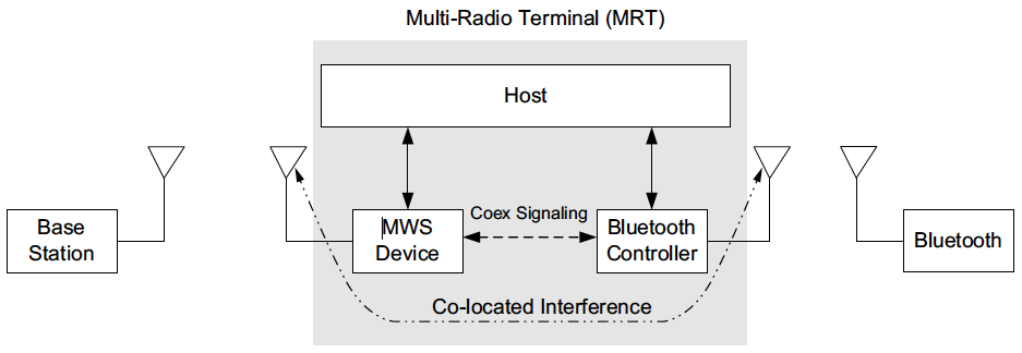 Figure 7.1: MWS coexistence architecture
Two types of solutions have been considered:
- In the first solution, both Bluetooth transmissions (TX) and receptions (RX) are constrained by collocated MWS activities. Solutions of this type are called Pure TDM (Time Division Multiplexed) Mode.
- In the second solution, only Bluetooth receptions are affected by collocated MWS transmissions and Bluetooth transmissions do not impact the operation of the collocated MWS.
- Solutions of this type are called Hybrid Mode and are achieved, for example, by using steep roll-off Band Select Filters (BSFs) for the ISM band in the Bluetooth transceiver.
- Hybrid Mode applies where the Bluetooth transmission’s effect on MWS is sufficiently reduced via filtering that the Bluetooth device can transmit during the MWS downlink time. This requires a frequency guard band between the Bluetooth and MWS operational frequency ranges as well as constraints on both the Bluetooth BSF and the MWS BSF. The requirement for a time domain solution still remains, but only to protect Bluetooth reception.
These solutions are facilitated by an MWS coexistence signaling mechanism (see [Vol 7] Part A) and multiple transport layers (see [Vol 7] Part B and [Vol 7] Part C).
Figure 7.2 shows how Bluetooth activity can interfere with every MWS reception opportunity and similarly how MWS transmissions can interfere with Bluetooth reception. In the example shown in Figure 7.2 the Bluetooth device in the MRT is operating as the master of a piconet. Blocks marked with an “M” are single slot master transmissions and those marked with an “S” are single slot slave transmissions. The times at which reception by the MWS device may be corrupted by Bluetooth transmissions are marked with a red shade. The times at which receptions by the Bluetooth device may be corrupted by MWS transmissions are also marked with a red shade.
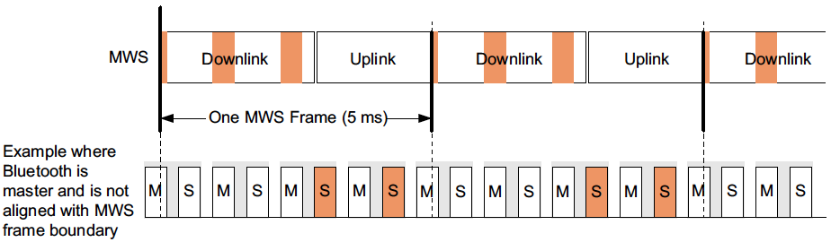 Figure 7.2: MWS receptions interfered with by uncontrolled Bluetooth transmissions
Even with the best relative timing relationship (when the Bluetooth slot boundary is aligned with the MWS frame boundary), the Bluetooth radio in the MRT suffers reduced transmission and reception opportunities due to time multiplexing with the collocated MWS radio. As a result, there is a high probability that the remote scanning device will not be able to receive the page or inquiry IDs within the current timeout. One example is shown in Figure 7.4
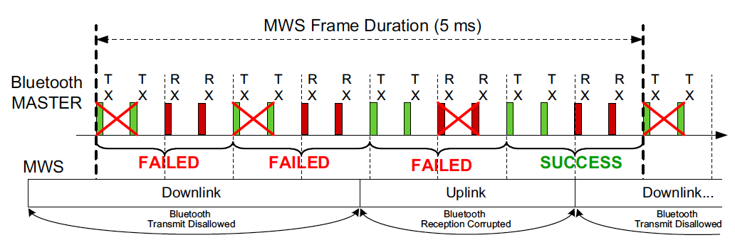 Figure 7.4: Bluetooth radio can suffer inquiry/page failures
When the inquiry or paging channel sequence gets repeatedly punctured, Train Nudging can be used to add an additional offset to the clock bits in order to shift the channel sequence.
Based on the pattern of slots that are not available for scanning, Generalized Interlaced Scanning can be used to tune the phase of the second scan during a back-to-back scan.
SYNCHRONIZING BLUETOOTH WITH AN EXTERNAL TIMING SOURCE
This section provides an example to illustrate the synchronization of the Bluetooth CLK with an MWS system so that the Bluetooth slots line up with the Downlink and Uplink times of the MWS system. The external frame in this example is LTE TDD Frame Configuration #1 and special subframe configuration #1; however the same mechanisms can be used for any external TDD/TDMA protocol. The example shows a time span of 10 ms.
[Vol 7] Part A defines the timing of the MWS frame as a fixed offset from the FRAME_SYNC (FS) signal in the coexistence signaling. FS can be defined by the Host as any specific offset within the MWS frame.
- For a piconet master, the most useful position for FS is the boundary between the uplink and the following downlink. This is because the master needs to transmit in a master slot during the uplink and then receive in the following slave slot during the downlink. Putting FS at this boundary allows the master to easily align its Bluetooth clock to put it between these slots.
- The situation is reversed in a slave: FS is most useful on the boundary between the downlink and the following uplink.
The HCI command HCI_Set_External_Frame_Configuration ([Vol 4] Part E, Section 7.3.81) is used to describe the MWS frame timing. This knowledge, together with FS, allows the Bluetooth Controller to align the Bluetooth clock with the MWS frame timing so as to minimize the effect of mutual interference. This is illustrated in Figure 7.6. The red ovals show slot pairs where both MWS and Bluetooth transmit and receive simultaneously and so do not interfere with each other. The MWS frame structure includes a downlink portion (“D”), an uplink portion (“U”), and a special portion (“S”) that includes a downlink and uplink portion separated by a guard period (“GP”).
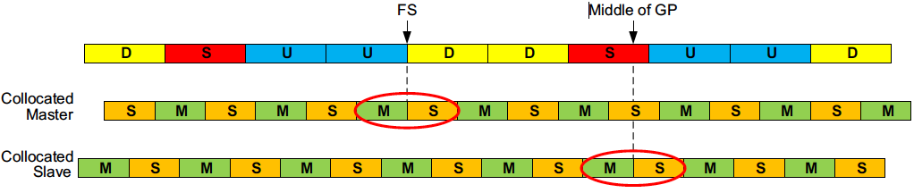 Figure 7.6: Alignment of MWS frame timing and Bluetooth clock
PICONET CLOCK ADJUSTMENT
As discussed in the previous section, aligning the MWS and Bluetooth clocks correctly greatly improves throughput on both technologies. The master has two mechanisms at its disposal to mitigate misalignments.
Coarse Clock Adjustments can be used to move the Bluetooth CLK using the LMP_CLK_ADJ PDU. The clk_adj_us parameter is used to align the slots with the MWS alignment point indicated by the FRAME_SYNC signal. The clk_adj_slots parameter can be used to move the CLK several slots forward in time. This can be useful to align e.g. eSCO. Coarse Clock Adjustment is expected to be used only rarely, for instance at MWS connection or when the MWS frame timing changes due to roaming. Coarse Clock Adjustment can only be used when all slaves in the piconet support it.
The other option for the master is to use Clock Dragging. This is a method of slowly adjusting the phase of the clock backward or forward by making the slots a few μs shorter or longer, respectively, until the desired CLK phase has been achieved. It should be noted that this is a very slow rate of adjustment, as it is designed to allow a legacy device to track the change, and therefore Clock Dragging must not be done at a faster rate than the maximum natural drift between devices. For this reason its main use is to facilitate small corrections over time if a misalignment with the MWS system is detected. If any device is connected that does not support Coarse Clock Adjustment, slowly moving the slave using Clock Dragging is the only option.
It is recommended to let the collocated device be the master, when possible, as it can react much faster to correct misalignments. If a slave is the collocated device, doing a role switch to make it master may be worth considering. Alternatively a slave can send a Piconet Clock Adjustment Request LMP packet to the master. The master then has the option to perform a Coarse Clock Adjustment, Clock Dragging, or to reject the request.
SLOT AVAILABILITY MASK (SAM)
Slot Availability Mask (SAM) allows two Bluetooth devices to indicate to each other time slots that are available for transmission and reception. The SAM slot map specifies the availability or otherwise of Bluetooth slots. A slot could be unavailable because of external conditions (e.g., MWS coexistence) or internal conditions (e.g., scatternet commitments). SAM does not impose new mandatory rules for the scheduling of BR/EDR time slots. Instead, it merely provides information which allows Controllers to refine their scheduling of Bluetooth slots to improve performance.
SAM slot maps are calculated by the Controller itself based on its scheduling requirements. There are no HCI commands defined specifically for SAM, merely LMP sequences that enable devices to exchange maps and indicate the map in use. The HCI commands HCI_Set_External_Frame_Configuration (see [Vol 4] Part E, Section 7.3.81) and HCI_Set_MWS_PATTERN_Configuration (see [Vol 4] Part E, Section 7.3.85) and real-time signals (e.g., MWS_PATTERN_Index or FRAME_SYNC) provided by the Coexistence Logical Interface (see [Vol 7] Part A) contain information concerning the appropriate SAM_Index and SAM anchor point to use for MWS coexistence; these may therefore trigger these LMP sequences.
A Controller may choose to perform a Piconet Clock Adjustment before initiating an LMP_SAM_SWITCH sequence so as to increase the number of slot pairs available per MWS frame.